VN
VN


 08/07/2026
Thematic
Decree No. 136/2020/NĐ-CP: Fire Dampers
22/06/2023


On November 24, 2020, the Government issued Decree No. 136/2020/NĐ-CP detailing certain articles and measures for the implementation of the Fire Prevention and Fighting Law, as well as the Law amending and supplementing certain articles of the Fire Prevention and Fighting Law. Section 5, Appendix VII of this Decree provides guidelines for the fire-resistant components (fire doors, fire walls, fire dampers, fire curtains) that are subject to fire prevention and firefighting inspection.
NỘI DUNG BÀI VIẾT
Fire Damper Inspection Standards
A fire damper is a device with a mechanical structure installed in the ductwork of an air distribution system, used for smoke extraction. It can be automatically or manually controlled to prevent the passage of flames. The construction of a fire damper includes the body, blades, and a heat-activated mechanism.
The standards for testing the fire resistance of fire dampers include:
- ISO 10294-1:1996 – Fire resistance test – Fire damper for air distribution system – Part 1. Test Method
- ISO 10294-2:1999 – Fire resistance test – Fire damper for air distribution system – Part 2. Classification, criteria, and field of application of test results
- ISO 10294-3:1999 – Fire resistance test – Fire damper for air distribution system – Part 3. Guidance on the test method
- ISO 10294-4:2001 – Fire resistance test – Fire damper for air distribution system – Part 4: Test of thermal release mechanism
According to ISO 10294 standards, fire dampers are classified into 4 types: E, ES, EI, EIS. Among these, E stands for integrity; I stands for insulation; S stands for leakage classification (smoke, gas). The leakage classification is defined in ISO 10294-1:1996; ISO 10294-2:1999; ISO 10294-3:1999 standards.
Fire damper meeting inspection standards
What defines a fire damper that meets the standards?
A fire damper product meeting standards needs to adhere to the following reference criteria:
- Designed with a circular, rectangular, or square shape.
- Constructed with multiple parts, such as the damper body, spring, fuse link, blades, shaft, etc. Additional motorized components may need to be added. Notably, the fuse link must meet the standards specified by the Vietnam Fire and Rescue Police Department.
- The damper body should be made from galvanized steel or stainless steel with a thickness ranging from 0.8 to 1.5mm.
- The damper shaft should be made from high-temperature-resistant steel.
- Regarding the dimensions of the fire damper, they can vary based on the requirements of each piping system.
- It should be coated for rust protection and thermal insulation.
Instructions for conducting inspections on fire dampers
Step 1: Prepare the test sample
– Size: The test sample of a fire damper is typically the largest type in terms of width and height, representing the batch of fire dampers that are intended to be produced based on this test sample. The test sample should represent the intended real-world use of fire dampers, including all essential components that could impact the sample’s performance during testing. The test results from the fire damper sample can be applied to smaller-sized fire dampers in terms of width, height, and length while maintaining the same technical specifications as the test sample.
– Quantity: For each proposed test, at least 2 fire damper samples need to be collected, with all necessary accessories for testing. In cases where the fire damper sample is entirely symmetrical and depending on the intended installation position of the fire dampers in reality, one sample can be used for testing.
– The test sample structure must include the heat-activated mechanism. If the heat-activated mechanisms are intertwined in a sequence with the basic heat-activated mechanisms and can demonstrate that they do not hinder the activation of the basic mechanism, then a single heat-activated mechanism test is sufficient.
– Real-world installation guidelines: The proposing entity for the test must provide the testing unit with detailed installation methods for placing the damper sample within the testing device’s support structure, suitable for the expected real-world installation of fire dampers.
To ensure the broadest application scope of test results, when designing the test sample and selecting the support structure, it must adhere to the requirements outlined in ISO 10294-1:1999 standards. The proposing test entity must provide specific dimensions of the constituent parts of the fire damper sample and the real-world installation positions and specifications to the testing unit.
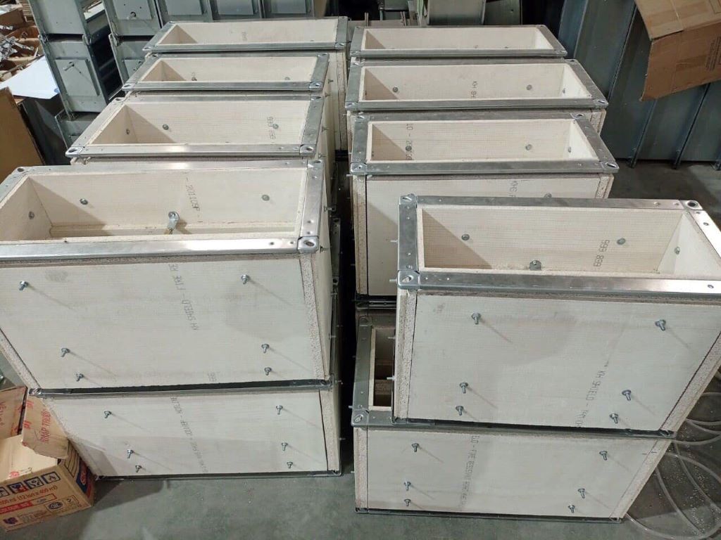
Fire Dampers Applying KH Shield Panel in IBST Testing Session
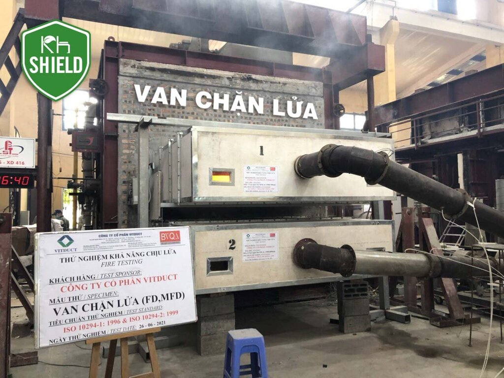
Step 2: Testing and Determining Test Results are carried out according to the following procedure:
- Measurement and pre-test inspection: The test sample’s geometric dimensions are inspected based on the technical documentation provided by the proposing testing entity, including: shape, geometric dimensions, construction materials of the fire damper; type and technical specifications of the heat-activated mechanism.
- Test procedure: The fire damper, along with any attached equipment, is either built into or directly attached to, or positioned at a distance from, a representative fire-resistant construction part through a duct section. The test starts when the fire damper is in the open position, allowing the heat-activated mechanism to come into contact with combustion chamber conditions. Temperatures are measured, and the integrity of different parts of the test structure is monitored throughout the test. The airtightness of the fire damper system is directly measured by the airflow when maintaining a constant pressure of 300 Pa in the closed fire damper state. In special applications, greater negative pressure can be used. If fire test conditions are not specifically defined during fire testing and with deviations, the fire test only provides a limited assessment of the heat-activated mechanism.
- Sample installation: The test sample installation must follow the guidelines provided by the proposing testing entity and align with ISO 10294-1:1996 standards.
- Conducting the test:
– Fire resistance test
Before conducting the fire test, perform 50 cycles of opening and closing the fire damper (representing about two testing and operating cycles for each fire damper per year) to identify any mechanical damage to the fire damper. The fire test for the fire damper sample is carried out as outlined in Section 9 – ISO 10294-1:1996, including the following steps:
- Secure the fire damper in the open position and place the test sample in the combustion chamber.
- Connect the test sample to all required measurement devices according to ISO 10294-1:1996.
- With the fire damper fully open, set up the exhaust fan system to generate an air velocity of 0.15 m/s through the open fire damper. This velocity can be measured using a pitot tube, Venturi, or other suitable device placed within the measurement duct. The air velocity must be maintained with an accuracy of ±15%.
- Turn off the exhaust fan while maintaining the settings implemented above.
- Start the burner. Begin the timer and activate the measurement devices.
- Open the ventilation fan immediately after igniting the burner.
- When the fire damper is in the closed position, adjust the exhaust fan to maintain a negative pressure of 300 Pa (or higher) in the connecting duct, corresponding to the combustion chamber. Record the time at which the fire damper closes. If the fire damper cannot be closed within 2 minutes from the start of burner ignition, the test is stopped.
- Maintain and record test values as specified in Section 9.8 of ISO 10294-1:1996.
Requirements: The test results for the inspected sample are specified in Table 1 – ISO 10294-2:1999.
– Heat-activated mechanism test (for fire dampers with heat-activated closing and opening mechanisms)
- The equipment and tools for testing the heat-activated mechanism are defined in Section 5 – ISO 10294-4:1999.
- Conduct the test according to Section 5 – ISO 10294-4:1999.
5. Determining Test Results:
– Integrity (E): Measured in minutes, the test sample must continuously maintain its compartmentalizing function during the test without exhibiting any of the following conditions:
- Sample collapse or stable flame occurrence on the non-flame-exposed surface of the sample system for more than 10 seconds;
- Testing with a cotton pad in gaps, cracks, or holes on the non-flame-exposed surface of the sample system shows the occurrence of a stable flame;
- Formation of gaps allowing a ruler of size 6mm to pass through and move along a minimum segment of 150mm;
- Formation of holes allowing a ruler of size 25mm to pass through;
– Insulation (I): Measured in minutes, the test sample must continuously maintain its compartmentalizing function during the test without causing an increase in temperature on the non-exposed surface in contact with the fire, specifically:
- Increasing the average temperature by more than 1400K compared to the initial average temperature; or
- Increasing by more than 180o K compared to the initial temperature at any location, including the mobile heat measuring point (the initial temperature is the average temperature of the non-exposed surface at the start of the test).
– Leakage during fire test: Measured in minutes, the test sample must continuously maintain the level of smoke leakage after calculation and conversion according to the procedure outlined in ISO 10294-3:1999, which is less than or equal to 360 m3/h.m2.
– Heat-activated mechanism test (for fire dampers with heat-activated closing and opening mechanisms): Measurement results must comply with the requirements specified in Section 4 – ISO 10294-4:1999.
The fire damper test results from the sample can be applied to fire dampers with smaller dimensions in terms of width, height, and length, but they must maintain the same technical specifications as the test sample.
Top-Quality Fire Dampers Meeting Standards
Some experts also provide recommendations:
“Companies need to carefully select and research fire-resistant and insulation materials for their constructions. Prioritize choosing manufacturers that can meet the standards of QCVN 06:2021/BXD and Decree No. 136/2020/NĐ-CP.”
Currently, statistics in the market show that there are only 4 units providing tested and certified fire damper solutions. Among them, Mr. Hoang Ngoc Chien – Director of Vitduct Corporation, one of the manufacturers of certified fire dampers, has the following comments and evaluations:
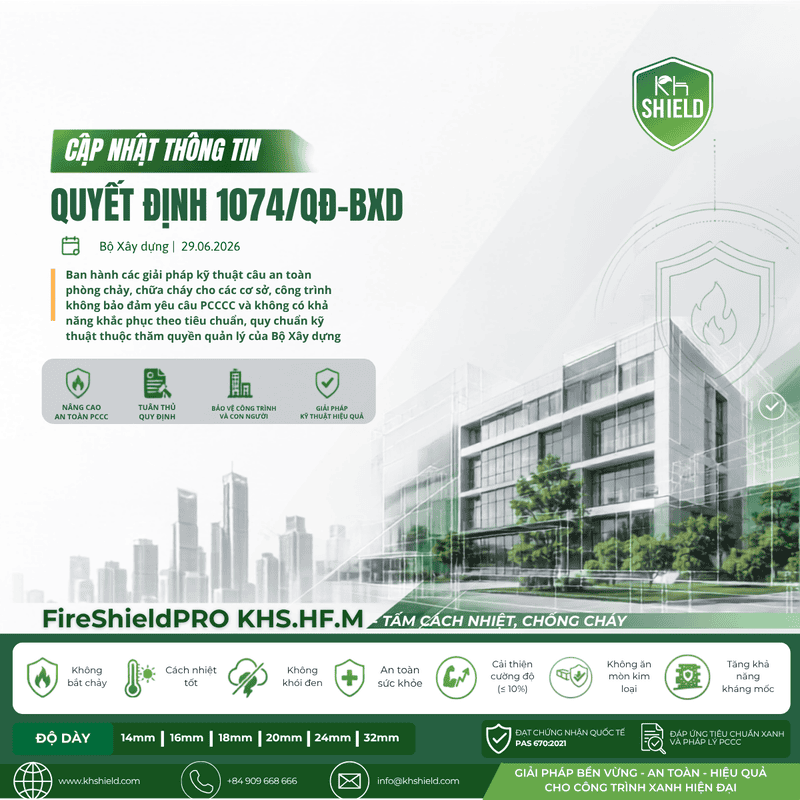
“The fire-resistant duct products, as well as the fire dampers from Vitduct, are a combination of metal and insulation material, specifically the KHS.HF.M insulation board. These products possess the following characteristics: achieving EI rating, durability, resistance to moisture and water, environmentally friendly, and generating no toxic smoke when exposed to fire.”
The KHS.HF.M insulation board, along with the KHS.FA fire-resistant board by KH Shield, proudly accompanies four fire damper supply units to create high-quality products that meet the Fire Prevention and Fighting regulations set by the Ministry of Construction. This collaboration offers effective fire and insulation solutions for various projects. The fire damper products are constructed using the KHS.FA fire-resistant board and the KHS.HF.M insulation board, meeting fire resistance standards at multiple levels: EI30, EI45, EI60, and EI90.
To learn more about the tested fire damper solution, please provide your information via email at info@khshield.com or contact our hotline at 0909 668 666. The KH Shield team will address your inquiries and provide specific guidance for you.
Update the latest topic


Update highlights


Register for consultation
Consultation on fire and explosion prevention solutions